Wednesday, April 7, 2010

COMPUTER/VOICE/REMOTE CONTROLLED RELAY


The Relay & Remote

Hi every one. I am back with another project.This is a relay circuit used to control real world a.c appliances using d.c 5v .The circuit I used Is from some other size but the idea of modifying it to be controlled by voice is mine.

The logic is quiet simple, there is a relay which is connected to the switch pins of the a.c appliance and other part is connected to a diode and d.c 5v which is the actual trigger. When we supply d.c 5v to the circuit it switches on the appliance connected to it.

Instead of simple 5v supply through a battery I planned to use my voice controlled car's circuit and program[modified for this one].
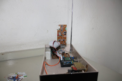
R/c Car's Transmitter Circuit

So now the same circuit sends +5v to the relay upon receiving voice signals which further switches the appliance.

I have connected the relay in such a way that I can now plug in the appliance direcly into the circuit so there is no hassle of connecting the switch wires.

I have made two identical circuits for connecting two devices at a same time.

The relay circuit is also connected to a wireless reciever so that it can even be controlled with voice and motion sensor circuit!

This can now be used as an automation system for my room if programmed further!


Wednesday, December 9, 2009

MOTION CONTROLLED R/C CAR

The Sensor

Sounds exciting right, i had the same excitement in making and playing it. I used the same computer controlled r/c car for this project.

In this project I have managed to control my r/c car through a motion detector that i built at home. The motion detector is tied on the hand and connected to the remote controller of the r/c car.

The idea behind this motion sensor is very simple and logical. We all know that for a circuit to work it must be closed, the push buttons in the car's remote close the circuit and make the car work.

The same idea is applied in this motion detector, instead of push buttons I used a set of screws and a metal washer[a thin ring put in between nuts and bolts to make them tight]. Three screws are drilled in a row on a plastic sheet and a washer is put freely on the middle screw, touching only the middle one. When tilted the washer touches a side screw and thus establishes a connection between the middle and a side screw acting as a switch.

This sensor is connected to the controller's switch connections and now acts as a real motion sensor switch when tilted in some direction.

I had to make two sensors i.e one for driving front and back and one for direction. After many trials and fine adjustments I placed all the parts on a plastic piece and glued it together.


The motion sensor can be connected with any toy or relay to control them with motion of hands!


Monday, November 30, 2009

Voice Controlled Car


The Bluetooth ear piece(The Actual Controller)
I wanted to control my computer controlled r/c car by some other way than remote buttons, so I planned to control it with my voice.

I did not have to make any changes in the hardware but had to design a new software.I used the Microsoft sdk4.1 for the voice support in my vb program. The program is similar to the first one, just a few changes and some new functions.The command buttons are triggered with voice commands which are pre-defined.

I have used a wireless mic(bluetooth) to input the voice into the program.When I speak a command then the sdk first anylizes it and sends it to the vb program, then the program matches the command with the pre-defined commands and triggers the respective command button.
Finally the program sends the commands to the Usb board - Transistor - r/c remote - The car.

I hope that I can do much more with this car !
Hope you liked the post.


Wednesday, April 8, 2009

COMPUTER CONTROLLED R/C CAR


The Car
After working for quite some time I managed to control an r/c car with my laptop.
I had this car lying around in my cupboard and thought of doing something cool with it.
This is a cheap car with digital controller so they have simple push buttons for making the car work.they have four basic functions i.e FRONT, BACK, LEFT, RIGHT.
The Car's Transmitter
First thing was to modify the car's controller so that it could be connected to the computer.The buttons on my cars controller were simple micro push buttons that upon closing the circuit would connect the ground to the IC. After finding out the 0V contacts and active[4v] on the transmitter I soldered wires to them.

Now for connecting these wires to the laptop i needed a usb controller and a circuit. The first step was to purchase a usb controller, so I ordered the DIGIBEE from www.pc-control.co.uk and got it shipped to Nepal.

The digibee upon receving signal from the laptop would switch on one of it pins and would give +5V output.So first of all I needed to make a circuit to convert these signal to ground for these i used simple resistors (470 ohms) and BC547 transistors. These transistors in return ground the active points on the transmitter when they recieve a signal from the computer.

After the circuit was made and the usb board had come I connected them using male and female serial port connector [For easy removal and modification] and fitted the circuit into a nice box.
I also connected the controllers wires to another serial port connector and connected it to the circuit.
THE FINAL CONTROLLER BOX

I finally connected the whole circuit to my laptop and controlled it with my program through which I had tried controlling the car earlier.The car finally worked wirelessly.

I have programmed the car in visual basic 6.0. It is a simple program made using simple commands and a supporting dll.

I hope that I can do much more with this car.

Hope you liked the post.